- CYPE >
- english >
- products >
- soil retention elements >
- embedded retaining walls


A program for site and civil works that carries out the design and Code check of embedded retaining walls of the following types: generic of any material, reinforced concrete slurry, reinforced concrete in-situ piles, steel sheet piles, and mini pile screens, incorporating the design and detailing of the reinforcement for the reinforced concrete types.
Modules
Three modules are available to design and check specific types of walls. These modules can be acquired together or separately:
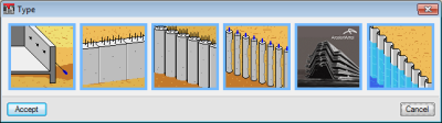
- Reinforced concrete retaining walls
Analysis, design and reinforcement of reinforced concrete, concrete pile and mini pile retaining walls.
- Steel sheet pilings
Analysis and design of ArcelorMittal Catalogue and generic steel sheet piling.
- Worst case slip circle
More information on this module can be found in the Safety checks section.
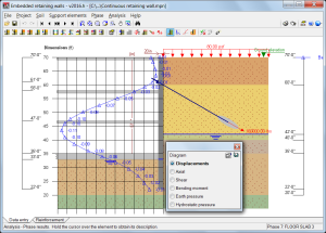
Construction Phases
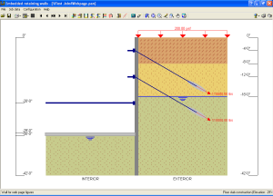
One can define the different phases or stages of construction, indicating:
- Different depths of excavation.
- Struts or braces.
- Passive anchors (temporary or permanent).
- Active anchors (temporary or permanent).
- Foundation at the bottom of the excavation.
- Floor slabs at different levels.
- Exterior loads applied on the ground.
- Loads transmitted by the basement floors.
- Loads at the top of the retaining wall.
- Shrinkage in the floors slabs.
- Temperature effects in the struts.
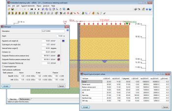
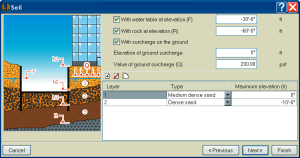
Soil
Users can define layers with different thicknesses with the properties obtained from the soils library, which contains the most common types of soils. User-defined soils can also be added.
Berms can be applied at the infill and excavations at the backfill in specific phases.
Users can indicate the water table and rock layer levels. The program also allows users to define impermeable layers to indicate there may be layers with very different permeability.
Analysis Model
The analysis model used to obtain the forces and displacements of the wall is based on soil-wall interaction methods, where the magnitude of soil pressures acting on the wall depends on its displacement. To calculate the action and/or reaction the soil produces on the wall, the wall is considered to have an elasto-plastic (non-linear) behaviour, obtained by approximating the real behaviour of the soil, which includes its plastification. The range of linear behaviour is associated with the lateral subgrade modulus concept of the soil, and the plastic range to the active or passive concept, depending on the displacement direction. Furthermore, support elements (anchors, struts and floor slabs) introduce a series of additional restrictions and actions, which are considered at the elevations at which they are located.
Since the solution of the problem depends on the deformation of the wall, the method requires the program to go through an iterative process until the equilibrium situation for iteration “i” is sufficiently close to that obtained for iteration “i+1”.
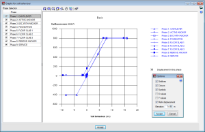
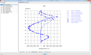
Results
See the diagrams for displacements, axial load, shears, bending moments, total earth pressure, and hydrostatic pressure. Additionally, you can see force diagrams for different phases, simultaneously, in various colors and showing the significant points and their values. The graphical results can be sent to a printer or make a DXF file.
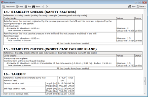
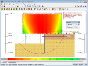
Safety checks
The program carries out three global stability checks:
- Ratio between the balancing moment of the passive pressure at the infill and the unbalancing moment of the active pressure at the backfill
This check is carried out for phases in which no supports have been provided for the wall, or maximum, only one, since the wall is already in equilibrium in other phases for which more than one support has been provided.
- Safety factor of passive pressure at the infill
As occurs in the previous check, this check is carried out for phases in which no supports, or maximum, only one has been provided for the wall, since the wall is already in equilibrium in other phases for which more than one support has been provided.
- Worst case slip circle
This check is carried out on retaining walls in phases where floor slabs have not yet been built, since the retaining wall is already in equilibrium in phases containing them.
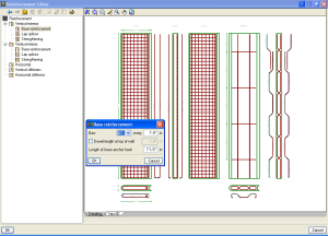
Reinforcement
The reinforcement of a concrete wall or in-situ piles may be user-defined or designed by the program from a reinforcement table. A Code check verifies that the reinforcement meets the Code requirements.
Generates complete reports that outline the checks performed on reinforced concrete sections.
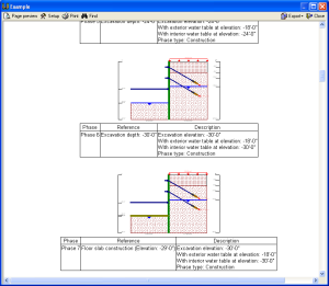
Reports
For all of the data, sketches of the construction phases, calculation results, force and displacement diagrams.
Reports can be sent to the printer or generated as a TXT, HTML, PDF or DOCX (Word2007 – Office OpenXML) file.
Prints the text in an organized layout with the graphics.
Seismic analysis
For the evaluation of pressures, the program employs a pseudo-static method, with the coefficients of dynamic pressure based on the Mononobe-Okabe equations.
Drawings
Of the detailing of reinforcement in reinforced concrete walls.
The drawings can also be exported in DXF and DWG format.
DXF and DWG construction details can also be added.
Assistant for various basement levels
Will help you to introduce the data for typical projects.
Tel. USA (+1) 202 569 8902 // UK (+44) 20 3608 1448 // Spain (+34) 965 922 550 - Fax (+34) 965 124 950